
How to Configure Voltage Transformers
- Check the "Configure Transformers" checkbox at the bottom of the AC electrical menu to open the Transformer section
- Make sure you have AC panels enabled in the AC wiring settings (transformers will be placed at the AC Panel, which determines where the voltage will be stepped up or down).

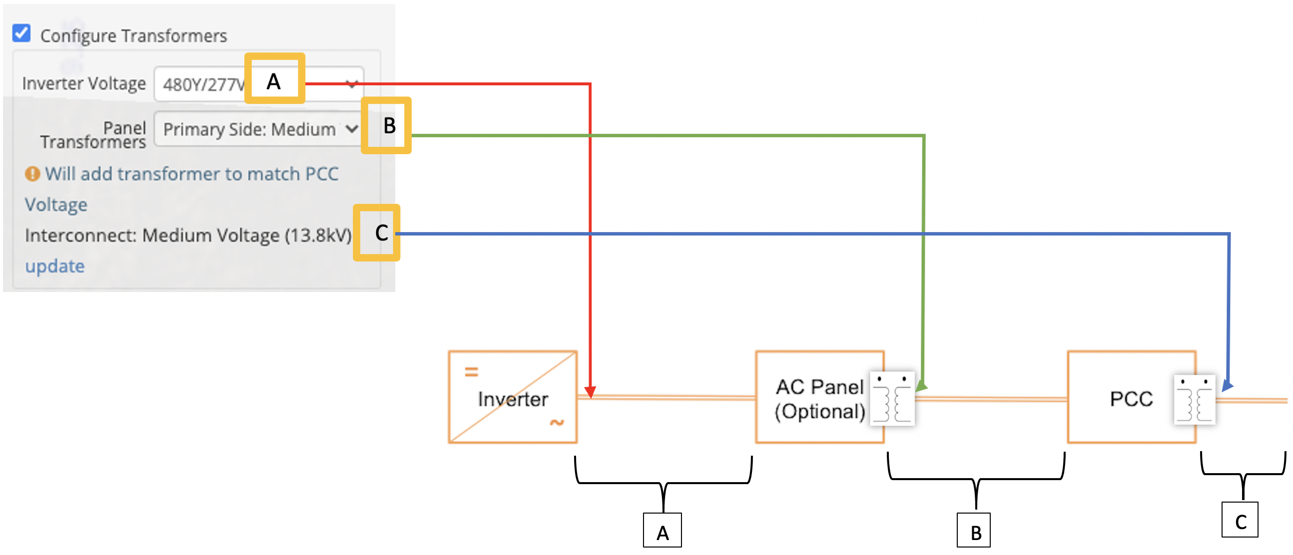
3. Set the inverter output voltage in the "Inverter Voltage" field (A)
4. Set the transformer output voltage in the "Panel Transformers" drop-down (C)
5. Set the grid interconnection voltage by clicking the AC Interconnect Voltage drop-down (D). Note: if the grid voltage is set you can change it by clicking the "update" link.
 For more control over the design of an AC system, HelioScope can configure transformers.
Efficiency and yield impact:
Transformers will change the operating voltage of the system, and therefore the wiring losses. Higher operating voltages lead to lower operating current - and therefore lower I^2R wire losses, although at this time the transformer efficiency is not factored into this calculation.
How Transformers Work:
The transformer design works by defining the voltages at each stage of the AC circuit. This includes the output voltage of the inverter, the output voltage from the AC panel (if applicable), and the interconnection voltage. Then, whenever there are changes in the voltages (defined by the user), a transformer will be added. Note that you do not directly add transformers to the design.
The output voltage of the inverter defines the AC Home Run (A) voltage. If the output voltage of the AC Panel is different, as defined in the “Panel Transformer” (C) drop-down menu, then HelioScope will include transformers at the AC Panels ( Primary Side of the transformer is the connection tied to the facility/utility grid). Similarly, if the grid voltage at AC Interconnection (D) is different from the voltage in range C, then an additional transformer will be included at the PCC.