This document is designed to help designers understand the DC wiring lengths in their Projects in HelioScope.
Conductor Lengths in the Bill of Materials
The Bill of Materials provided by HelioScope shows the different component types (Name) and amounts.
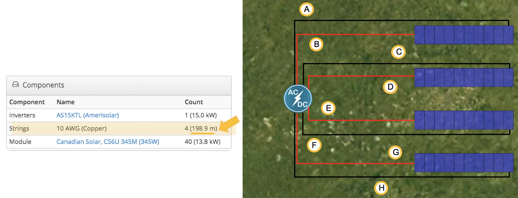
The Project below has 40 modules, in 4 strings of 10 modules, connected to 1 inverter.

Conductor lengths are calculated with two conductors over their distances in the Designer. These lengths are based on the beginning and end module of each string and the distance to the inverter.
In the example Project below the total conductor lengths shown in the Bill of Materials on the Report and in the Single Line Diagram will be the result of A+B+C+D+E+F+G+H for a total 198.9 m.

Conductor Lengths for wire resistance calculations
HelioScope models wire losses based on the resistance and current on the conductors each hour.
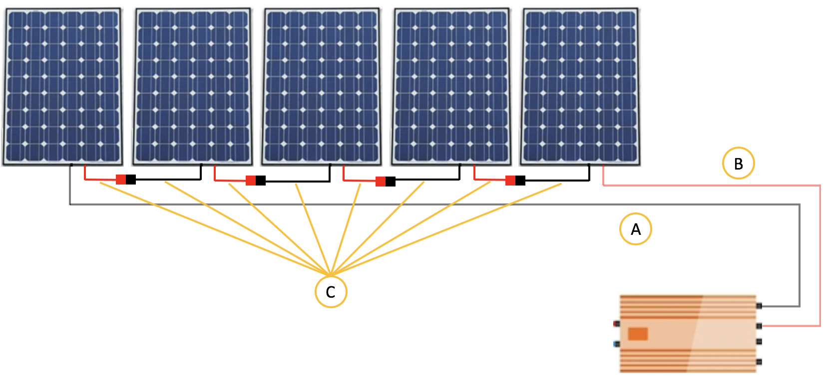
Modules on a string are connected to each other through conductors, often known as "whips". For the wire resistance calculations, the total length of the conductors will be defined by the length of the conductor from the first and last module of each string to the inverter, and the total length of the "whips" that are used to connect the modules to each other on the string.
The total length will be A+B+C. Where C is the sum of all the "whips" that are part of every module, used to connect the modules to each other.

