HelioScope is commonly used for ground-mount array design. For those users who are new to designing ground mount systems, this document provides typical ground mount design principles:
| Parameter | Function | Typical Values |
| Racking | Defines whether modules are tilted up, or flush with the underlying surface | Fixed tilt |
| Azimuth | The directions modules in a Field Segment face. Note that this is different from PVsyst, where the equator is 0°. | 180° (due South) |
| Tilt | The tilt of the modules in the Field Segment. | 10°-30° |
| Setback | Distance around the perimeter of the Field Segment where modules cannot be placed. | 10' |
| Orientation | Determines if modules are set in portrait or landscape. This should be set according to the racking product design. | Portrait / Landscape |
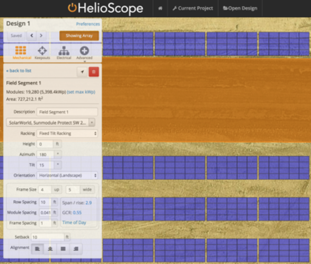
| Frames | Blocks of modules that are laid out in a single plane. The example seen below is comprised of frames 4 up by 5 wide. | 4 up by 1 wide (if landscape) |
| Row Spacing | Front-to-back spacing between rows for site access. This can also be set based on a target Ground Coverage Ratio. | 10' |
| Frame Spacing | Lateral spacing between frames for thermal expansion. | A few inches to 1' |
| Electrical | HelioScope will automatically select inverters to target a 1.25 DC/AC ratio. For conductor sizing, many developers target voltage drop values under 1.5-2.5% on both the AC and DC circuits. | DC/AC ratio of 1.25 |

Figure 1: Typical Ground Mount Design
Frame Size
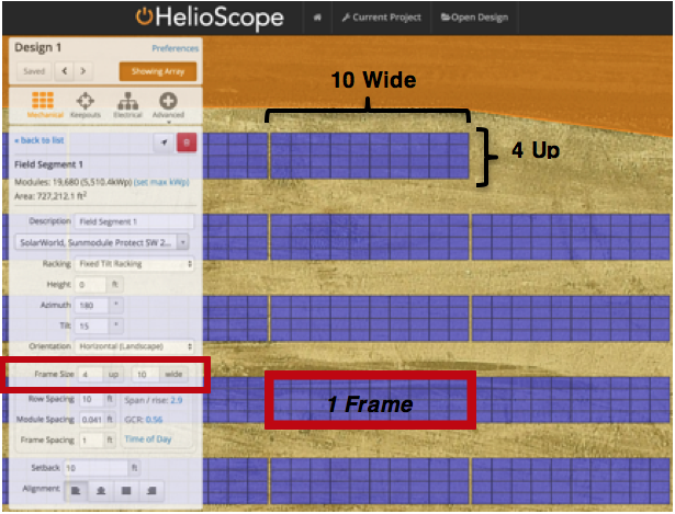
Frames (often called “tables”) are an important element of ground-mount arrays. To create a ground-mount design, users should set their modules “up” to the desired depth of the bank (seen below as 4 up), and the width according to the length of the table (seen below as 10 wide).

Figure 2: Frame Sizes in HelioScope
Center Alignment
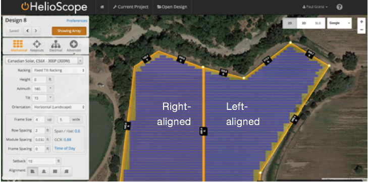
Users often want to design Ground Mount arrays centered on an access path. With HelioScope’s Alignment function at the bottom of each field segment, this can be accomplished by splitting ground mounts into two field segments, one left-aligned and one right-aligned, to achieve the desired walkway-adjusted effect. To make sure the rows are aligned to each other on each side of your access path, use the align to click function.

Figure 3: Centrally Aligned Array
Single-Axis Tracker
Single-axis Tracker is a premium feature available at an additional cost. To request trial access to this feature, please contact sales@helioscope.com. You can learn more about the feature on this help page.
